DESCRIPTION
We offer a brand-new device to measure
mechanical stress in constructional materials and metal and alloy materials. European patent for
invention EP 1251343 "Method and device for
mechanical stresses measurement"
was obtained in 2006. It measures
uniaxial and biaxial stress on the basis of speed change effect of hardness
tester ball springback. This device is absolutely safe in comparison with other
ones based on other physical principles, for example, on X-ray method. Measurements provide reliable information about
stress state of material surface coating with thickness form 0.15 till 0.5 mm depending on the type
of metal and alloy.
This device is especially important for use in the aircraft industry. Many assembly parts and elements are shotpeened and peenformed in the process of manufacture of underframe, hull, foil, fins. The Almen method was normally used to control these finishing processes and their stability – use of witness samples. However, nowadays, it is necessary not only to know and be sure about the process stability, but also about the element processing quality.
Normally, the X-ray method is used to determine the stress in surface of parts and elements. The most important shortcoming of this method is a poor accuracy due to the physics of the X-ray, which, with reliable construction of the Bragg diffraction pattern, penetrates to the depth not more than 25 μm. This error can reach (50-100) Megapascal (МPа). As a result, the averaging value for calculations may be critical for the fatigue resistance factor and it does not guarantee the absence of unexpected destruction during the service life.
This is the reason why sudden aircraft accidents happen nowadays. The proposed device helps to eliminate this problem. In fact, its measurement limits for the depth of stress are actually the same as the recommended depth of the surface plastic deformation and the depth of beneficial compression train created by this deformation during strengthening and peenforming (0.25-0.7 mm). When X-rays are used, no such concurrency is found and it creates additional problems. As nothing is known about the mechanical stress created in the entire thickness/depth of the processed surface layer inside the part. And this layer may ten times exceed the depth reached by X-rays. Besides, portable x-ray devices are not flexible enough for measurements, their functions are limited and their use requires taking special measures to protect the personnel and the operator.
The offered device can be redesigned or adjusted specifically to control some finishing process, for example, to strengthen an aircraft engine vane with glass microballoons or a device version to control the stress field directly in the wing panel cover during its strengthening or peenforming. It is completely safe and flexible in use.
The principle and essence of measurements will be the same in both the cases, but the devices differ in the program adjustment of the finishing of different materials and different depth of deformation.
We believe that the device may be extremely useful for control of mechanical stress for manufacturing of modules and divisions of space platforms and satellites as welding is the main technological process in production of space station bodies and shells. The unfavorable conditions in the open space, the cyclic processes of heating-cooling and great radiation require a high quality of manufacture. Nowadays the welding stress is not controlled in any way in production of bodies and shells. Such control, undoubtedly, would increase safety of staying on space platforms. Not only aircraft companies show interest in our invention, but also the companies, which build oil- and gas pipelines to control welding stress. The data on distribution of stress fields inside an element enables evaluation of this element service life. In total it will result in the increase of fatigue resistance and reliability of aviation equipment.
The purpose of the device is:
- to measure, assembly and operating tension in important structures and junction points of aircrafts and watercrafts;
- to monitor stress in materials used in the near welding areas of important structures and, first of all, pipe installations under pressure and gasholders;
- to detect places where structural elements are most likely to break because of fatigue due to continuous cyclic use;
- to correct and adjust fatigue design by means of finite elements method (FEM) for aircrafts.
Basic characteristics:
Measurement range: till 0.8 of material yield limit
Measurement error: till 3% of material yield limit
Operating temperature range: from -15 °C till +30 °С
The device consists of mechatronic sensor having diameter 32 mm and length 164 mm and computer. The sensor is connected with the computer with cable. Its weight may vary from 320 till 410 gram depending on its completing units. Computer may be in the form of notebook which is for portable usage or in the form of stationary computer for laboratory research. Amount of measurements is not limited. Time of one measurement is not more than 5 seconds. Computer contains programs for calculations of data from sensor and programs for graphing and construction of stress diagrams.
It can be used for measurements of mechanical stress in products made of the following materials:
- construction steel
- alloyed steel
- aluminum alloy
- cuprum alloy
- titanium alloy
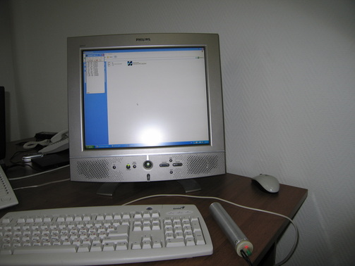
Device
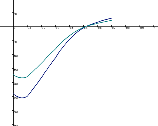
The diagram of measurement of residual stresses for alloy Д16Т
Video
